The determination of a heat flux  is based on the measurement of a temperature drop (temperature difference) Δϑ across a thermal resistor.
 The thermal resistance of a layer depends on its thickness Δx and thermal conductivity λ.
 The thermal resistance of a heat flux sensor should be as small as possible to minimize the associated change of the measured heat flux. Therefore very small temperature differences have to be measured. This is carried out by a thermopile, i.e. a series connection of several hundreds of thermocouples.
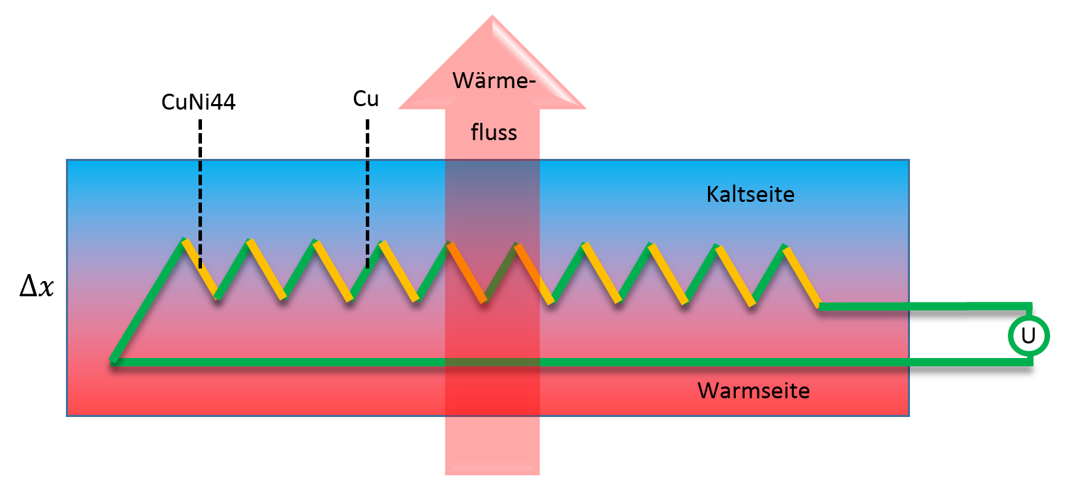 With the known number of thermocouples N and the Seebeck-coefficient α of the thermocouple the heat flux can be calculated:
 The measured thermovoltage U is proportional to the heat flux. Since some of the parameters can’t be determined with sufficient accuracy and can change as a function of time, heat flux sensors have to be calibrated at regular time intervals. The calibration constant c relates the heat flux with the measured thermovoltage.
 It specifies the heat flux density that must flow through the heat flux sensor in order to generate a voltage of 1 mV. Due to the high sensitivity of our heat flux sensor (corresponding to small calibration values), they typically deliver voltages in the millivolt range. These can be conveniently recorded using standard measurement technology. Since the source resistance (internal resistance) of the heat flux sensor is also relatively low, shielded cables are not usually required for connection. The installation of a heat flux sensor always causes a disturbance in the original temperature field. The reduction in heat flux density due to the additional thermal resistance can be easily estimated and is usually negligible. However, the one-dimensionality of the temperature field is also disturbed (part of the heat flows around the heat flux sensor). As a result, the heat flux at the sensor is lower than at its center. During calibration, however, suitable measures are taken to ensure that a homogeneous heat flux passes through the entire sensor
To reduce measurement errors caused by this, there is a wide edge strip around the thermocouple area (the active surface), known as the guard ring. It is constructed in exactly the same way as the actual heat flux sensor, but without thermocouples.
Any reduction in heat flux is limited to the guard ring and therefore has no influence on the measurement result.
It specifies the heat flux density that must flow through the heat flux sensor in order to generate a voltage of 1 mV. Due to the high sensitivity of our heat flux sensor (corresponding to small calibration values), they typically deliver voltages in the millivolt range. These can be conveniently recorded using standard measurement technology. Since the source resistance (internal resistance) of the heat flux sensor is also relatively low, shielded cables are not usually required for connection. The installation of a heat flux sensor always causes a disturbance in the original temperature field. The reduction in heat flux density due to the additional thermal resistance can be easily estimated and is usually negligible. However, the one-dimensionality of the temperature field is also disturbed (part of the heat flows around the heat flux sensor). As a result, the heat flux at the sensor is lower than at its center. During calibration, however, suitable measures are taken to ensure that a homogeneous heat flux passes through the entire sensor
To reduce measurement errors caused by this, there is a wide edge strip around the thermocouple area (the active surface), known as the guard ring. It is constructed in exactly the same way as the actual heat flux sensor, but without thermocouples.
Any reduction in heat flux is limited to the guard ring and therefore has no influence on the measurement result.
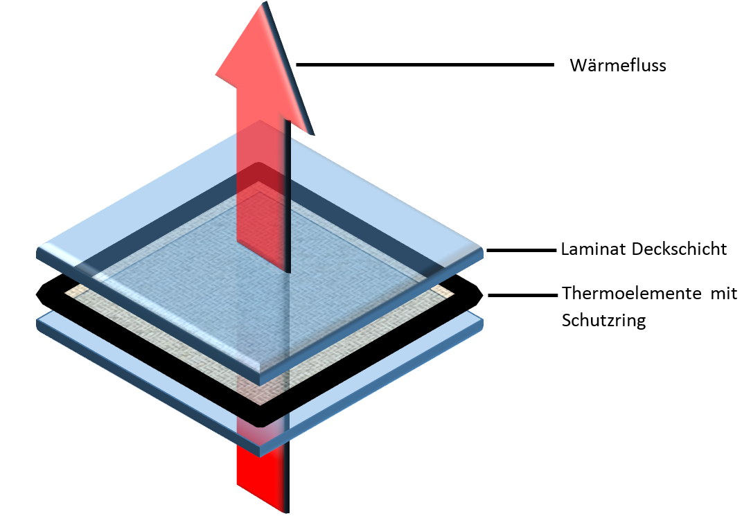 The required thermal resistance is achieved by a strip-shaped carrier material onto which the thermocouples are applied. In the rigid heat flux Sensor, these thermocouple chains are embedded in epoxy resin and covered by a laminate layer. In the flexible types, the casting compound is a silicone rubber.
Due to the CTE of the carrier material, the temperature dependence of the thermal resistance, and the temperature dependence of the Seebeck coefficient, the calibration value depends on the operating temperature of the sensor. This dependence was determined for our sensors using a guarded hot plate apparatus. The results of these measurements show an almost linear dependence of the calibration values on temperature. Consequently, to improve the accuracy of heat flux measurements over an extended temperature range, a correction can be applied. measurement .
The required thermal resistance is achieved by a strip-shaped carrier material onto which the thermocouples are applied. In the rigid heat flux Sensor, these thermocouple chains are embedded in epoxy resin and covered by a laminate layer. In the flexible types, the casting compound is a silicone rubber.
Due to the CTE of the carrier material, the temperature dependence of the thermal resistance, and the temperature dependence of the Seebeck coefficient, the calibration value depends on the operating temperature of the sensor. This dependence was determined for our sensors using a guarded hot plate apparatus. The results of these measurements show an almost linear dependence of the calibration values on temperature. Consequently, to improve the accuracy of heat flux measurements over an extended temperature range, a correction can be applied. measurement .
is based on the measurement of a temperature drop (temperature difference) Δϑ across a thermal resistor.
The thermal resistance of a layer depends on its thickness Δx and thermal conductivity λ.
The thermal resistance of a heat flux sensor should be as small as possible to minimize the associated change of the measured heat flux. Therefore very small temperature differences have to be measured. This is carried out by a thermopile, i.e. a series connection of several hundreds of thermocouples.
With the known number of thermocouples N and the Seebeck-coefficient α of the thermocouple the heat flux can be calculated:
The measured thermovoltage U is proportional to the heat flux. Since some of the parameters can’t be determined with sufficient accuracy and can change as a function of time, heat flux sensors have to be calibrated at regular time intervals. The calibration constant c relates the heat flux with the measured thermovoltage.
It specifies the heat flux density that must flow through the heat flux sensor in order to generate a voltage of 1 mV. Due to the high sensitivity of our heat flux sensor (corresponding to small calibration values), they typically deliver voltages in the millivolt range. These can be conveniently recorded using standard measurement technology. Since the source resistance (internal resistance) of the heat flux sensor is also relatively low, shielded cables are not usually required for connection. The installation of a heat flux sensor always causes a disturbance in the original temperature field. The reduction in heat flux density due to the additional thermal resistance can be easily estimated and is usually negligible. However, the one-dimensionality of the temperature field is also disturbed (part of the heat flows around the heat flux sensor). As a result, the heat flux at the sensor is lower than at its center. During calibration, however, suitable measures are taken to ensure that a homogeneous heat flux passes through the entire sensor
To reduce measurement errors caused by this, there is a wide edge strip around the thermocouple area (the active surface), known as the guard ring. It is constructed in exactly the same way as the actual heat flux sensor, but without thermocouples.
Any reduction in heat flux is limited to the guard ring and therefore has no influence on the measurement result.
The required thermal resistance is achieved by a strip-shaped carrier material onto which the thermocouples are applied. In the rigid heat flux Sensor, these thermocouple chains are embedded in epoxy resin and covered by a laminate layer. In the flexible types, the casting compound is a silicone rubber.
Due to the CTE of the carrier material, the temperature dependence of the thermal resistance, and the temperature dependence of the Seebeck coefficient, the calibration value depends on the operating temperature of the sensor. This dependence was determined for our sensors using a guarded hot plate apparatus. The results of these measurements show an almost linear dependence of the calibration values on temperature. Consequently, to improve the accuracy of heat flux measurements over an extended temperature range, a correction can be applied. measurement .